
Samsung Washer stopped spinning – WF80F5EBP4W – DC41-00189A
2 years ago my wife and I bought a Samsung washing machine. Thought we would get for the money spend a reliable washing machine who should for the money spend last at least 5 years. Turning out that afer one year the machine stopped spinning, or I should say it looked like the trum tries to spin and had no power, because it only twisted for like a 1/2 an inch in both directions.
So I went through trouble shooting manuals, like did you balance the clothing the right way, is the seive clean. You know the normal things you would expect. Nothing helped. I called Samsung because the machine was still under warranty and made an appointment for a service technican. Technican arrived 1/2 a week later or week and instantly replaced the cuircut board. I thought mmh either the guy is a genius, or this was not the first main circuit board changed. After turning on the machine, the machine right away worked!
Woow. So my hope (yes sometimes you can hope) Samsung just had some issues with some batches of circut borads and now I have one who will last.
Unfortunately NOT.
Right after warrenty ended the machine stopped spinning again or I should say it sometimes worked for like 10 min and the machine stopped until we restarted the program, then worked for another 10 min and eventually after 6 hours we had clean clothing.
So again I first thought, misbalanced clothing, went through troubleshooting, did a re-calibration program, which you can apparently start pressing a few buttons. Yes nice thought but no did nothing.
I called the Samsung hotline again and got given two options:
- We right away will send you a service in the next week, which will be expensive
- We give you a phone number with one of our service companies and get a quote
I decided for number 2 and called the service company. They offered me a service with no warranty of success and basically right away said, if you spend a few bugs more you get a new machine. WHAT. This machine was around 450€ and a little bit over 2 years old.
I said I will think about and come back to you. At this point we decided either I find out how to repair it, or we just buy a new one. So not much too loose.
Next thing I did was to open the machine, which you can do by just open the top cover which has 2 screws at the back. Before of course I unplugged the machine!
Attention: The machine is full of electrical capacitors, which are still loaded after unplugging. I am a trained electrician and have equipment to measure voltages!! I am not responsible if you injure yourself by an electric shock!!!
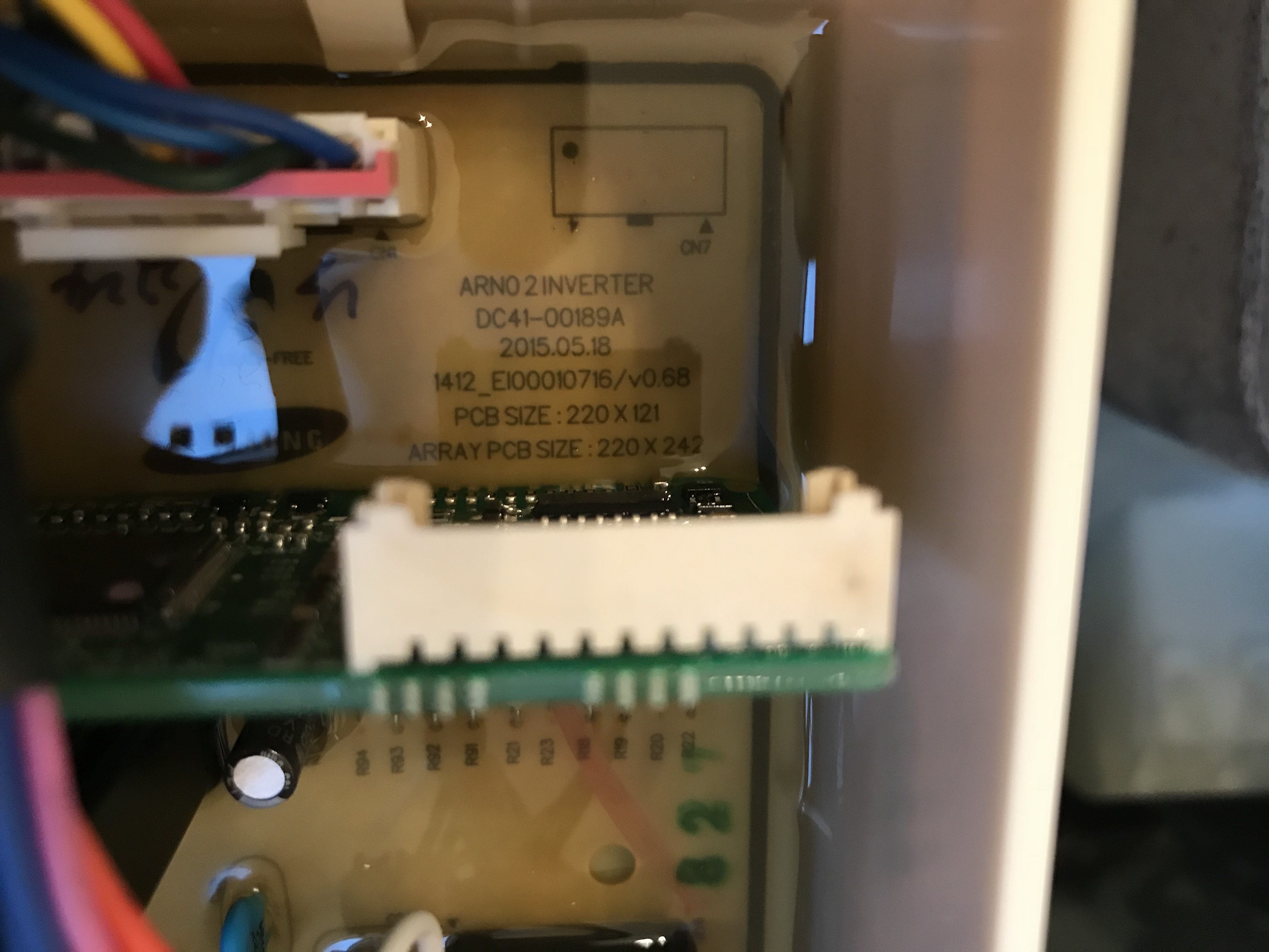
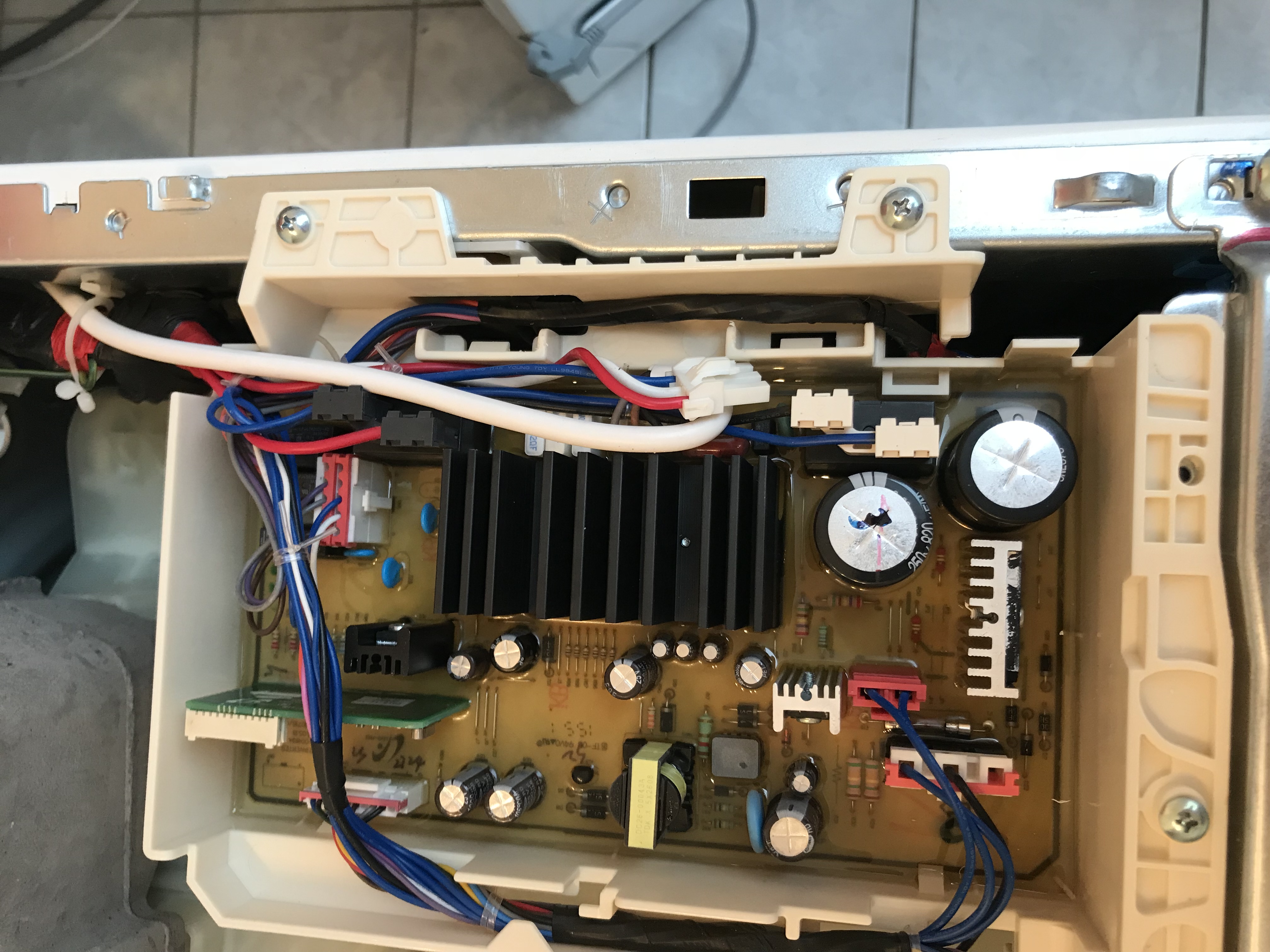
The ciruit board model number is DC41-00189A
First think I recognized when taking a look at the circuit board, it is filled with a soft silicon. Instead thought was, wow so either they wanted to prevent people fixing this or it should keep the parts not vibrating causing disconnections. I did not see any bulbed capacitors either who would give me an indication that they are broken.
So fixing ( I thought ) of the circuit board was off the table and I researched how much a replacement board would be. Last price given was around 180€. Which is by the way the second most expensive part in the entire machine I think after the motor. And I placed an order since at this point I did not find any more information on the web at this point. At least I would save the installation costs.
Then I came across this youtube video
The person explains what on his board broke and also how you get to the place on that board. Thank you soooo much at this point for making that youtube video.
First you need to bring a ton of patience. This is because the board is filled with silicon and you need to get this partially away. You also need to cut out the board, because the silicon acts like a glue and really keeps the board in the plastic box.
So here were my steps:
- Measure that the capacitors have no load anymore. The capacitors are filled with sqrt(2) * 230V. So measured them at that point against ground, to make sure that I do not get electrified right away. And I waited a good half hour or hour.
- Take a picture of all cables and connectors you might need it later.
- I unplugged all connectors to the board carefully. Some of them have a hook, so make sure you hold down the button of the connectors or put a small scredriver underneath the plastic hooks. Also now make sure that the cables are loosly hanging around the plastic box now.
- Take the screws off the top of the plastic box and tild the plastic box so that it comes out of the machine.
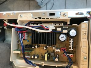
- You should now have the circuit board in a plastic box in front of you.
- If you think this was hard, now comes the hard part. You need to now get the board out of the plastic box. Luckily someone did that in that video before me, I would have never that otherwise. I took a metal saw. Yes you are right a metal saw and cut away the end of the plastic box holding the ciruit board.
- You now see that I cut the end just off, but the board is still tightly in the plastic box. You need cut around between the circuit board and the plastic box from the top. I cut through the small plastic hooks holding the board in the plastic box. I cut around a good 5 times making sure I really go no silicon stopping me to the board out here.
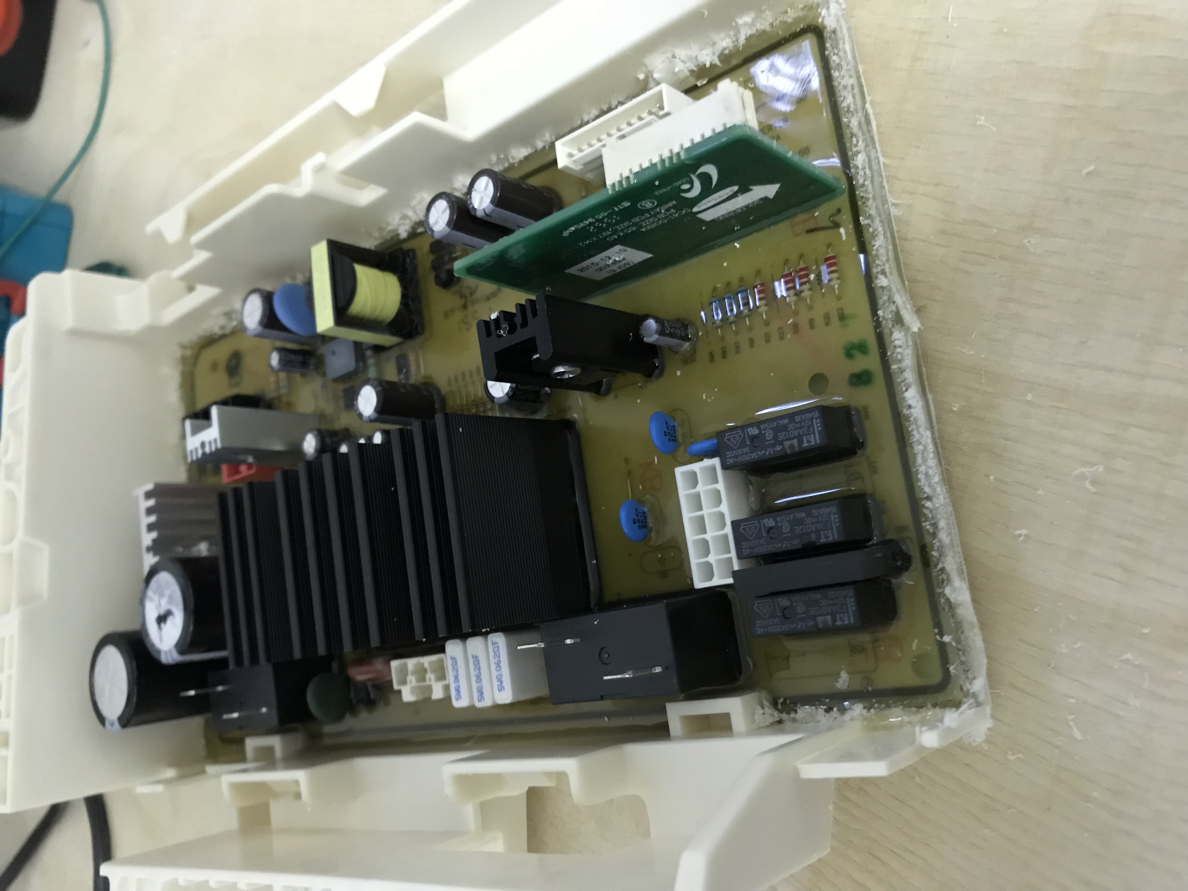
- This is the super patience part. You need to work extremly slow and do not speed up. You need to get a scraper between the board and the plastic box where you cut away the end. The silicon there is super gueing and does not come off easily. Pulling on the ciruit board breaks it. If you pull you either have to fix the board later, or buy a new one. So patience is a virtue!. I slowly worked a thin metal scraper underneath the board and slowly made progress pushing the scraper in. This took a good 1,5 hour if not more. So take your time!!! Also if you look take a look to the picture above, there are at least 2 IC sitting on the bottom side of the ciruit boards. When you push a scraper underneath you will feel resistance or like a block. I pulled gently on the board and managed to get the scraper underneath.
- Eventually make scraper was not long enough anymore, but I had still silicon hanging. Now I used a thin long metal plate and pushed it further underneath. It takes really a long time, but eventually the board comes off.
- You should now have the circuit board in front of you and need to get the silicon off the bottom. At least partially. I did not scrape (with my fingers) the silicon off completly, because the ciruit boards needs to get back into the box without vibrating when the machine is running.
- So what breaks on the circuit board actually. Answer: The traces and cold soldering and silicon running between the cooling element and the IC unit underneath.
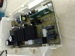
There are 2 areas of problems.
One is the big cooling element. There is silicon between the cooling element and the IC who is getting cooled. The guy in the video shows that pretty good. So to fix the silicon preventing the IC getting cooled, I also scraped / cut away silicon on top of the circuit board right around the cooling element.
Second area is on the bottom of the board. Here the traces broke who connected the IC unit mounted against the cooling element. You can use a multi meter and push the probes through the silicon that way you can find broken traces without getting the silicon off.
Also there are disconnects in the area where the big capacitors are and the fuse. Those neeed to be just re-soldered. - To dismount the cooling element you need to open up the holes on the bottom side of the board. They are clearly marked but sitting of under silicon. I broke away some circuit board material with a scredriver and the screws show up.
You also need to unsolder the cooling element. It is soldered to the board. Take a philips screwdriver and you can get the cooling element off - I then cleaned the cooling element put new paste on the cooling element so that the heat is “floating” from the IC to the cooling element.
- I remounted the cooling element against the circuit board now. Here please be gently! You will crack the IC otherwise
- Now I re-soldered the IC and the cooling element. This revealed the big problem to me. The traces had disconnects right between the die and the traces connecting the big IC.
To save you some time. I eventually ended up opening the machine again and resolder it again with flexible wire. I was not able to see the cracks in the traces, but they more or less all had cracks and the IC was not connected.
It should then look as:
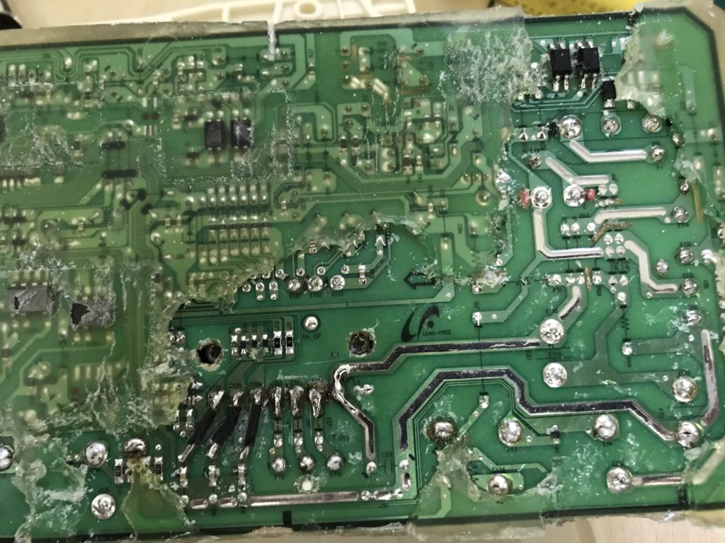 You can also now see the areas I re-soldered. There are some areas which to my belive the traces are designed as fuses. Do NOT “over solder” them. You also see where I left silicon back on. You can also see the two holes I created on the board.
 - I now moved the circuit board back into the plastic box and put some cable strippers around. The board should stick even without back in the box. I even did not put the end plastic on. I know this is a bit geeky, But I had no better idea at this point.
- Put the plastic box back into the machine, put the screws in and put all connectors back on.
- I at this point took a look if all ground connectors along the machine are connected. Unbelievable but I found disconnected ground connectors.
- Put the cover on the machine and put the screws in
- Plug in the machine and or meausure that there is no electricity on the machine. You need to make sure that there is no power on the frame of the machine. I did not do a insolation measurement, because I do not own a device to do so.
- Test run. I did a run on Rinsing and Spinning
- Our machine worked like a new machine for the last 5 month.

Leave a Reply
You must be logged in to post a comment.